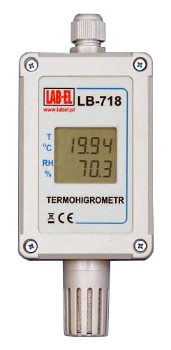
LB-718 Hytherograph with a Resolution of 0.01°C and Modbus RTU Support

The LB-718 hytherograph is designed for precise measurement of
temperature and relative air humidity in rooms. It can work
in a dusty environment because the sensors are surrounded by a filter.
The device talks with the measuring system using the industrial RS-485
Modbus RTU communication standard.
- Air temperature, resolution 0.01°C, uncertainty 0.1°C
- Relative air humidity, resolution 0.1% RH, uncertainty 2% RH.
- RS-485 Modbus RTU
- 7..28V DC 4mA
- -40.0…+85.0°C, recomended: 0..40°C
- 10…90% RH, recomended: 20…80% RH
- Polymas, ABS, IP65, 170x64x35mm

- measurement: temperature, relative air humidity
- robust and dust-proof housing
- Wide operating temperature range
- RS-485 interface, MODBUS RTU
- temperature resolution of 0.01°C
- PC software - LBX SCADA
Description
The LB-718T digital hytherograph is designed for air temperature and relative air humidity measurement in rooms. It may operate in extremely dusty spaces, thanks to the use of air-tight housing and suitable filter protecting the measuring sensor. It is a small, stationary thermometer, powered by an external source. Measurement data are displayed on a two-line LCD display; they may be displayed with a resolution of 0.1% RH and 0.01°C.
To make the measurements, the hytherograph uses data from the external Pt-1000 temperature sensor and the relative humidity capacitive sensor. On the basis of the known non-linear characteristics of the sensors and digital calibration data stored during calibration on the device storage memory, the built-in microprocessor calculates the current measurement results. The results are available in a digital form for the supervising data collection system via the RS-485 interface and MODBUS RTU protocol.
The LB-718 hytherograph is equipped with a digital RS-485 interface that allows the operation of up to 32 devices on one rail with a total length of up to 1,200 m. Thethermometer integrates the widely-known MODBUS RTU protocol, thanks to which the thermometer may operate in many systems based on this standard. In particular, the LB-718 hytherograph may be connected via the DE-311 Ethernet converter with the LBX software, serving as a central point of the LAB-EL monitoring system.
The hytherograph is equipped with jumpers used for setting the MODBUS address in the range of 1…32.
The output of the LB-718 hytherograph is made with screw clamps (4 camps — power, A and B lines), located inside the housing, to which a cable is led through an opening with a diameter of 7 mm.
The hytherograph does not feature mechanical calibration elements (e.g. potentiometers). The hytherograph calibration includes sending calibration data via a digital interface to the instrument’s permanent storage, obtained from the calibrated climatic conditions. It ensures convenience and high calibration accuracy as well as the stability of the device's metrological parameters over time.
In the standard version, the instrument is equipped with a sensor screen (impurities filter), type F3.
Calibration certificates
Each hytherograph, as per order, may feature an individual calibration certificate provided by LAB-EL Calibration Laboratory.
Dedicated software
This hytherograph may additionally come with an advanced software for Windows — the LBX software — enabling:
- presentation of current readings from devices;
- alarm monitoring and signalling;
- presentation of archived data — charts, reports, histograms;
- data archive management;
- access for remote clients.
Technical Data
Dane techniczne termohigrometru
| TEMPERATURE MEASUREMENT | ||
|---|---|---|
| Measurement uncertainty | +/- 0,1 °C | ±1 final digit |
| Measurement range | -40..+85 °C | |
| HUMIDITY MEASUREMENT | ||
|---|---|---|
| Measurement uncertainty | +/- 2,0 % | within the range of 10…90% ±1 final digit |
| +/- 4,0 % | outside the range of 10…90% | |
| Measurement range of LB-718 | 10..95 % | for temperatures up to +40°C |
| 10..60 % | for temperatures up to +70°C | |
| 10..40 % | for temperatures up to +85°C | |
| Measurement range of LB-718H | 0..100 % | for temperatures up to +60°C |
| 0..70 % | for temperatures up to +70°C | |
| 0..40 % | for temperatures up to +85°C | |
| MEASUREMENT READING | ||
|---|---|---|
| Parameter | Reading range | Resolution |
| Air temperature
|
-40,0..+85,0 °C | 0.01°C, optionally 0.1°C (configured with a jumper) |
| Relative humidity | 0,0..99,9 % | 0,1 % |
| RECOMMENDED CONTINUOUS OPERATING CONDITIONS *) | |
|---|---|
| Temperature range | 0…40°C |
| Humidity range | 20…80% |
*) Exceeding the recommended continuous operating conditions (e.g. when installing the device outdoors) requires the use of additional protective measures for the electronic part of the device against the eventuality of water entering the device (protection of the electronics with silicone or usage of additional external housing).
| POWER SUPPLY, MECHANICAL DATA | ||
|---|---|---|
| Voltage range | 7…28 V DC | |
| Power consumption | approx. 4 mA | without a terminator |
| External dimensions of the housing | 170 x 64 x 35 mm | |
| Material | plastics (polymas, ABS) | |
| Housing protection class | IP 65 | additionally limited by the protection class of the filter |
DIGITAL INTERFACE
RS-485 transmission parameters: 19,200 bps, 8 information bits, parity control — Even, 1 stop bit (19200/8E1) or (configured with a jumper starting with the firmware v1.0.1) 9,600 bps, 8 information bits, no parity control — none, 1 stop bit (9600/8N1)
MODBUS RTU protocol. Interface connection in the form of 4 screw
clamps, accessible after removing the device’s cover. Address set with
jumpers in the range of 1…32.
Description of available MODBUS registers
| INPUT REGISTER (READ SINGLE/MULTIPLE REGISTER) | |||
|---|---|---|---|
| The value defined as the register address is the same as the one that should appear in the Modbus data package in the address field. Sometimes the PC software adopts the Modicon convention and requires that the input register address be expanded by 30001 more than the value given in this document — e.g. the DEVID register would then have 30001. | |||
| Address | Designations | TYPE | Description |
| 0 | DEVID | WORD | Device type identification 0x0718 (hex format) |
| 1 | CPTB | WORD | Firmware version from the viewpoint of operation via MODBUS. In the event that the user’s software recognises firmware of a newer version (FVER register) than the supported one, it should — while reading this register (CPTB) — confirm that it is able to support the device. The version specified in the CPTB register is possibly the oldest version that the current firmware is backward compatible. Description correct for CPTB = 10000. |
| 2 | SNUM | WORD | Serial number of the device |
| 3 | FVER | WORD | Firmware version in the form of X.Y.Z, where: X — tens of thousands of FVER, Y — hundreds of FVER, Z — units of FVER. E.g.: for FVER = 21203, it is 2.12.3 |
| 4 | CONFIG | WORD | The value of a variable set by the manufacturer;
meaning of bits:
0: humidity measurement present 1: thermometer featuring wide range of temperature (E version: -200…+550) 2: temperature measurement averaging enabled (for the FLOAT type variable) 3: humidity measurement averaging enabled (for the FLOAT type variable) 4: temperature resolution of 0.01°C |
| 5 | STATUS | WORD | State of the device; meaning of bits:
0: ERROR_T — temperature measurement error 1: ERROR_RH — humidity measurement error 2: CFG_ERR — calibration error Remaining bits feature no meaning |
| 6.7 | T | FLOAT | Temperature |
| 8.9 | RH | FLOAT | Humidity |
| 10 | T_WORD | WORD | Temperature as a number in U2 code with a resolution of 0.1°C (the read-out value should be divided by 10) |
| 11 | T_WORD_AVG | WORD | Temperature — the same as above, but averaging |
| 12 | RH_WORD | WORD | Humidity as a number in U2 code with the resolution of 0.1% (the read-out value should be divided by 10) |
| 13 | RH_WORD_AVG | WORD | Humidity — the same as above, but averaging |
| 14 | CAL_YM | WORD | Date of the last calibration, LSB: year — 2000, MSB: month |
| 15 | CAL_DH | WORD | Date of the last calibration, LSB: day, MSB: hour |
| 16 | CAL_M | WORD | Date of the last calibration, MSB = 0, LSB: minute |
| DEVICE IDENTIFICATION |
|---|
| Read Device Identification 43/14 BASIC ID |
EXTENSIONS
By special order, the following set-ups are available:
- The LB-718Fn digital thermometer — version of sensors’ cover (according to description), the version is given if it is not F3.
INTERACTION WITH THE DE-311 ETHERNET CONVERTER
LB-718 devices may be connected to the DE-311 converter, thanks to
which the measurement data may be monitored by the LBX software via Ethernet.
Connection of the LB-718 with the DE-311 should be made according to
the following table:
| DE-311 | LB-718 | DC 7…28 V power unit | Signal description |
|---|---|---|---|
| 3 | A | Data + (B) | |
| 4 | B | Data - (A) | |
| 5 | - | - | Power - / GND |
| + | + | Power + |
Microswitch of the DE-311 converter should be in the RS-485 position:
| SW1 | SW2 | SW3 |
| OFF | ON | ON |
Other versions of the LB-718:
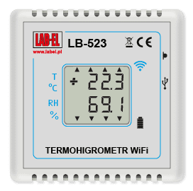
 Thermohygrometer LB-523
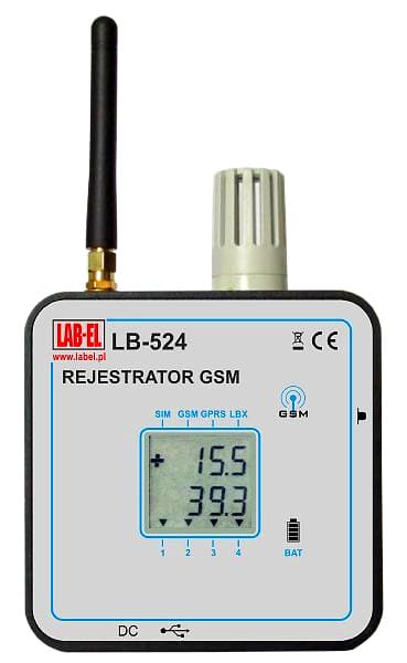
 Hytherograph LB-524


