LB-762 and LB-762A - Climate Controller -
Mushroom-Growing Microclimate Regulator
- functions: measurement, recording, regulation
- measurement: temperature, humidity, CO2
concentration, overpresure
- competitive price
- new version of the tried-and-tested LB-760A regulator
- extended measurement capabilities
- ‘turnkey’ installations
- LBX software to supervise the growing process
- new functions, new possibilities, innovations
- LB-762-IO
Additional Interfaces Module
- control
via portable tablet using Windows
- software update
- regulator settings made with the LBX software
- regulator
settings made with the LB-765 remote controller
Intended use of the controller
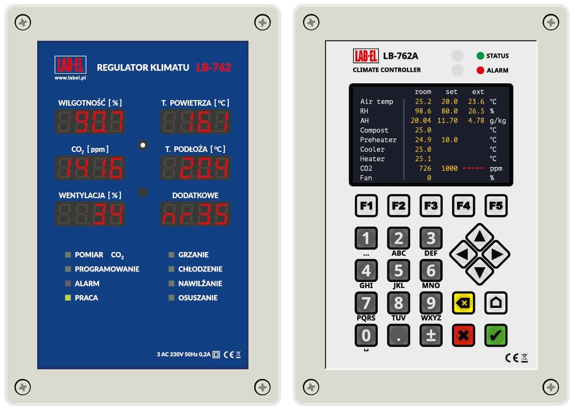
The LB-762 regulator is used for controlling a single mushroom-growing cellar. It provides all necessary measurements and control of the working devices in order to provide optimum climatic conditions for mushroom-growing.
The LB-762A regulator is a modernized version of the LB-762 regulator, in which the front panel with LED displays has been replaced with a new panel with LCD display and keyboard. The LB-762A regulator in relation to the LB-762 has the following additional functional features: a touch-colored graphic display allowing for programming the controller and a keyboard allowing for convenient data entry and activation of additional functions such as watering control.
In the case of a large facility, consisting of a greater number of growing cellars, each mushroom-growing cellar must be equipped with a separate regulator. In such a case there is the possibility of connecting all the regulators in a common measurement and control system. In such a system every controller for a mushroom-growing cellar operates independently, but it is possible to control all the regulators with one PC and one instalment of the LBX software. Additionally, it is possible to perform certain common operations for the whole system in mushroom-growing cellars — e.g. measurement of external air parameters or measurement of CO2 concentration.
The LB-762 climate regulator succeeds the LB-760A regulator, with a tried and tested track record over 10 years in a few hundreds of mushroom-growing cellars nationwide and internationally. The LB-762 regulator, in addition to all the functionalities of its predecessor, features many extra functions — e.g.: more inputs for measuring probes, more outputs for analogue servos (traditional) and digital Belimo MP-Bus servos, more relay outputs, Ethernet interface for data transmission.
Design
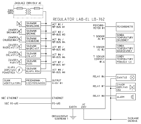
Figure 1 shows a layout of typical external connections for a single LB-762 mushroom-growing cellar regulator. The regulator should be connected with a set of suitable measuring probes and working devices in order to work properly.
Measuring probes
- Wet-and-dry bulb thermometer — used for measuring temperature and relative air humidity. The regulator may work with one or two wet-and-dry bulb thermometers (at least one is required for the correct functioning of the regulator). Adding one wet-and-dry bulb thermometer provides single-point measurement of the temperature and air humidity in the growing cellar. A second wet-and-dry bulb thermometer may be optionally used for measuring temperature and humidity in a different area of the growing cellar for a better averaging of the conditions in the cellar. Another function of the wet-and-dry bulb thermometer may be to measure air parameters in the blowing channel for adjusting the humidity and temperature of air flowing into the cellar.
- Chiller temperature — single thermometer informing the regulator about the chiller’s functioning.
- Heater temperature — single thermometer informing the regulator about the heater’s functioning.
- Air supply temperature — optionally, two thermometers informing the regulator about the temperature of air supplied to the climatic channel (before the chiller). The use of these thermometers is optional.
- Substrate temperature — 6 thermometers used for measuring temperature of the substrate in different areas of the cellar. It is not required to connect all 6 thermometers — the regulator works correctly with any number of connected thermometers (1–6), depending on requirements for a given installation.
- CO2 concentration — in order to measure CO2 concentration it is necessary to connect a separate, dedicated CO2 concentration meter. The connection of a dedicated CO2 meter is possible with every regulator (separate meter for each cellar) or one CO2 meter is used for a greater number of cellars (to reduce installation costs).
- External thermo hygrometer — in order to provide better functioning of the growing-cellar climate control mechanism, the regulator may use information about the parameters of the external air flowing into the climatic channel. It enables the direct use of this air’s characteristics (enthalpy and humidity mass) for controlling the climate in the cellar, without the use of working devices in the climatic channel, which reduces energy consumption. It is possible to connect a separate thermo hygrometer to every regulator or to use one thermo hygrometer for the entire system (which makes it possible to reduce installation costs, as the parameters of the external air are usually common for all cellars and a separate measurement in each cellar is not required).
- Additional universal temperature probe
Working devices
- Heating, cooling, humidification, pre-heater, pre-chiller and vapour valves — controlled with servos (some outputs are optional and in a given installation may not be present).
- Sprinkler systems for floor humidification and for watering
mushroom shelves, controlled by signals from the relay outputs of the
LB-762 regulator.
- Ventilation — a fan is used to circulate air; the fan’s motor is controlled with a suitable frequency converter (inverter). The frequency converter is an external device controlled by the regulator.
- Cellar lighting — the regulator may control the cellar lighting; this functionality is used during gasification, for example.
- Alarm signalling device — the regulator may signal alarm states (e.g. incorrect climate parameters in a cellar, various malfunctions, etc.). In order to signal an alarm, each regulator is equipped with a suitable relay output that may control an acoustic signalling device, for example. It is possible to connect the alarm signalization to each of the regulators separately or with a single connection for all the alarm outputs of all the regulators in a given installation, as well as one control system for one signalling device. The use of alarm signalling is optional. An alarm signalling is also possible via the LBX control software on a PC.
Arrangement of the system elements
Figure 2 shows a sample arrangement of measuring probes and executive devices in a mushroom-growing cellar and in an air-conditioner for the system of the full air-conditioning with the use of the LB-762 controller.
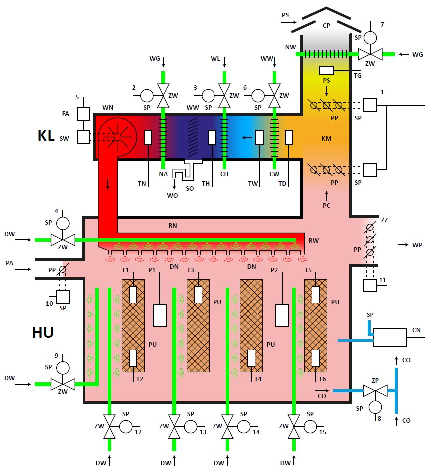 Figure
2. Scheme of an exemplary arrangement of measuring sensors and
actuators for full air-conditioning of the HU mushroom growing hall
with the use of the KL air-conditioning unit and the LB-762 series
controller.
Description of symbols in Figure 2: T1…T6 — measuring probes of
the substrate temperature; TD — measuring probe of the temperature
before the CW pre-cooler; TW — measuring probe of the temperature after
the CW pre-cooler; TH — measuring probe of the temperature after the CH
main cooler; TN — measuring probe of the temperature after the NA
heater; TG — measuring probe of the temperature after the NW
pre-heater; P1, P2 — wet-and-dry bulb thermometer; 1…10 — control
outputs from the LB-762 regulator (output functions: 1 — air; 2 —
heating; 3 — cooling; 4 — humidification; 5 — ventilation; 6 —
pre-cooling “2”; 7 — pre-heater; 8 — CO2 measurement; 9 - floor
humidification; 10 — vapour, 11 - outlet flaps with an actuator to
regulate the overpressure; 12, 13, 14 and 15 - successively watering of
the shelves PU); PU - 4 rows of shelves; CO — air consumption ducts for
the system of CO2 concentration measurement; ZP — air consumption
valve; PP — air choke valve; PC — circulating air; PS — fresh air; CP —
fresh air inlet; KM — mixing chamber; CW — pre-cooler; CH — main or
Freon cooler; WW — cold water for pre-cooling (e.g. from a well); WL —
main cold water (chiller) or Freon; ZW — water valve; SP —
proportionally acting servo; WW — water partial condensers; SO —
condensation siphon drain of the OW condensed water outlet; WG — hot
water; PA — vapour; NA — main heater; NW — pre-heater; WN — fan; FA —
inverter for controlling revolutions of SW fan motor; DW — inlet of
humidifying water; RW — water atomizers; RN — blowing-in sleeve; DN —
blowing-in nozzles; ZZ — return valve of WP air blown out of the
cellar, CN - overpressure sensor.
Data transmission network
In an installation where there is a larger number of controllers it is possible to connect them to form a data transmission network. Such a network can interact with a PC and control software. With the use of the data transmission network, additional functions may also be carried out:
- measurement of external air parameters (with the use of a single thermo hygrometer);
- common CO2 concentration measurement (when one CO2 meter serves a larger number of growing cellars).
The LB-762 regulator is equipped with two data transmission network interfaces: Ethernet and RS-485. The use of the right network depends on the conditions and requirements for a given installation:
- Ethernet — this network guarantees a very high data transmission speed (10 or 100 Mb/s). Due to the immense popularity of this type of network in all kinds of applications, it is easy to integrate with currently existing IT systems. The limit of the Ethernet network is the distance — one cable section (between two network devices, e.g. between a regulator and a switch) may not exceed 100 metres. This does not mean the network is limited in range — rek854.htmlwith the use of suitable network devices (switches, repeaters or even routers), the network may be extended to an unlimited area. The number of devices in the Ethernet network is relatively unlimited.
- RS-485 — this network provides a relatively slow data transmission, in comparison to the Ethernet (19.2 kb/s), but it boasts simplicity of cabling and a larger range without the need for using additional network devices (up to 1,200 metres). Thus the cabling of the network is simpler and slightly cheaper. A single RS-485 network is limited in the number of connected devices — up to 32.
Interaction with the LB-760 regulators
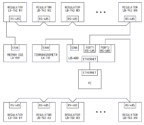
The LB-762 mushroom-growing cellar regulators may be used in systems in which the LB-760 regulators have been used until now. It is possible to build one common system, in which both types of regulators work, allowing the right system functions to be carried out, irrespectively of the type of regulator (e.g. common measurement of the external air parameters and cumulative system of the CO2 concentration measurement). Figure 3 shows the layout of a sample common installation with LB-762 and LB-760 type regulators, with the use of two separate RS-485 networks for both types of regulators. The layout with the Ethernet network is similar, but the LB-760 regulators remain connected with the RS-485 network, and for the LB-762 regulators the RS-485 network is replaced by the Ethernet network.
Cumulative measurement of CO2
In a measurement system consisting of larger number of regulators (both the LB-762, as well as LB-760 mushroom-growing cellar controllers), it is possible to make the CO2 concentration measurement in two ways:
- local measurement — each regulator is equipped with its own CO2 meter;
- cumulative measurement — one CO2 meter serves a larger number of growing cellars.
Connection of individual CO2 meters is quite costly; the use of cumulative measurement enables a reduction in installation costs. Figure 4 shows layout of a typical installation of a cumulative CO2 measurement by using a connection of LB-762 regulators with a control computer via RS-485 interfaces. The system consists of the following elements:
- CO2 concentration meter — used for measuring CO2 concentration in air supplied to individual cellars;
- pump — to suck the air out of individual cellars;
- valves — to open the air supply from individual cellars.
During the cumulative measurement the system opens vales for individual cellars in cycles, letting in only the air from one cellar in a given moment. Additionally, the CO2 concentration measurement of the external air may be incorporated in the system. This provides control over the correct functioning of the CO2 meter via fresh air. In order to make a cumulative measurement of the CO2 concentration, the continuous functioning of the control LBX software installed in a PC is indispensable.
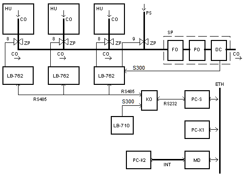 Figure 4. System layout
of
the
cumulative measurement of the CO2 with a connection via
RS-485 interface.
Figure 4. System layout
of
the
cumulative measurement of the CO2 with a connection via
RS-485 interface.Description of symbols in Figure 4: CO — air consumption
ducts; 8…9 — control outputs
from the LB-762 regulator (output functions: 8 — CO2
measurement; 9 — external CO2 measurement); ZP — air valves;
PS — fresh air (external air CO22 measuring box
(featuring: FO —
dewatering filter; PO — air pump and DC — CO2 measurement);
KO — LB-480
converter; LB-710 — thermo hygrometer for measuring external air
parameters; SP — CO concentration
meter); PC-S — computer controlling functioning of the system (server);
ETH — local Ethernet network; MD — modem/router; INT — Internet
network; PC-K1 — additional operating station (computer in internal
network); PC-K2 — additional operating station
(computer with external access, via the Internet).
An alternative solution, delivering much faster system functioning, is the connection of LB-762 regulators with the PC-S control computer, with the use of an Ethernet interface. The layout of such a connection is shown in Figure 5. The external LB-710 thermo hygrometer may be connected to the system via various converters: the LB-480 converter (then, other functions of this versatile hub may be used) or via a simple LB-375 converter connected to the USB interface of the PC-S computer server.
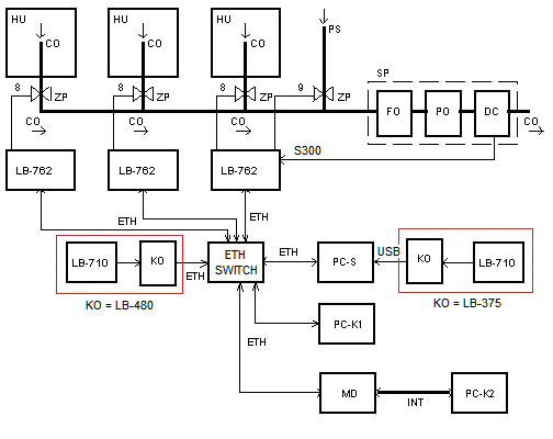 Figure 5. System layout
of
the
cumulative measurement of the CO2 connected via an Ethernet
interface
Figure 5. System layout
of
the
cumulative measurement of the CO2 connected via an Ethernet
interfaceDescription of symbols in Figure 5: CO — air consumption ducts; 8…9 — control outputs from the LB-762 regulator (output functions: 8 — CO2 measurement; 9 — external CO2 measurement); ZP — air valves; PS — fresh air (external air CO2LB-480 converter or LB-375 converter; LB-710 — thermo hygrometer for measuring external air parameters; SP — CO2 measuring box (featuring: FO — dewatering filter; PO — air pump and DC — CO2 concentration meter); PC-S — computer controlling functioning of the system (server); ETH — local Ethernet network; MD — modem/router; INT — Internet network; PC-K1 — additional operating station (computer in internal network); PC-K2 — additional operating station (computer with external access, via the Internet); KO - option.
Functioning
Output adjustment signals are the results of calculations made in PID adjustment procedures, on the basis of set values and actual measured values of: temperatures, humidity and CO2 concentration. For test and start-up purposes it is possible to manually program the values of output signals. Control of the executive devices via regulators is carried out smoothly (with the use of proportionally acting servos) or via the simulation of a smooth adjustment, based on the on/of principle with variable coefficient of filling, through supplying the voltage of 230 V / max. 1 A (heating, cooling, humidification).
The equipment software carries out a number of additional, special functions, e.g.:
- controlling in a way suitable for the various phases of mushroom-growing, e.g.: incubation, shock, yielding, evaporation, switch off;
- drainage of growing after watering;
- making it possible to chemically disinfect the cellar.
The design of the equipment and functioning of their control equipment has been devised in consultation with many experts in the field of mushroom-growing and is constantly developed in accordance with experience gained in mushroom-growing cellars, in which the LAB-EL regulators have now been working for many years.
The user of the LAB-EL regulators may update the software for the regulators and the software used by the control PC. Owing to the modern design of the regulators, it is possible to independently input the operation program into the regulators multiple times. For this purpose the user may download the latest software from the Internet (or provided on a CD), which loads the new operating program from the control PC to all the regulators one by one.
Advanced function systems are monitored by LBX software for PC, working with Windows, which was developed as an answer to changing user requirements, the appearance of the new HACCP production quality certificates and to keep up with the continuous advancement of computer technology. The advanced functions are presented in the LBX software description.
Installation and operating instruction for mushroom-growing cellar controllers and software are available from our website.
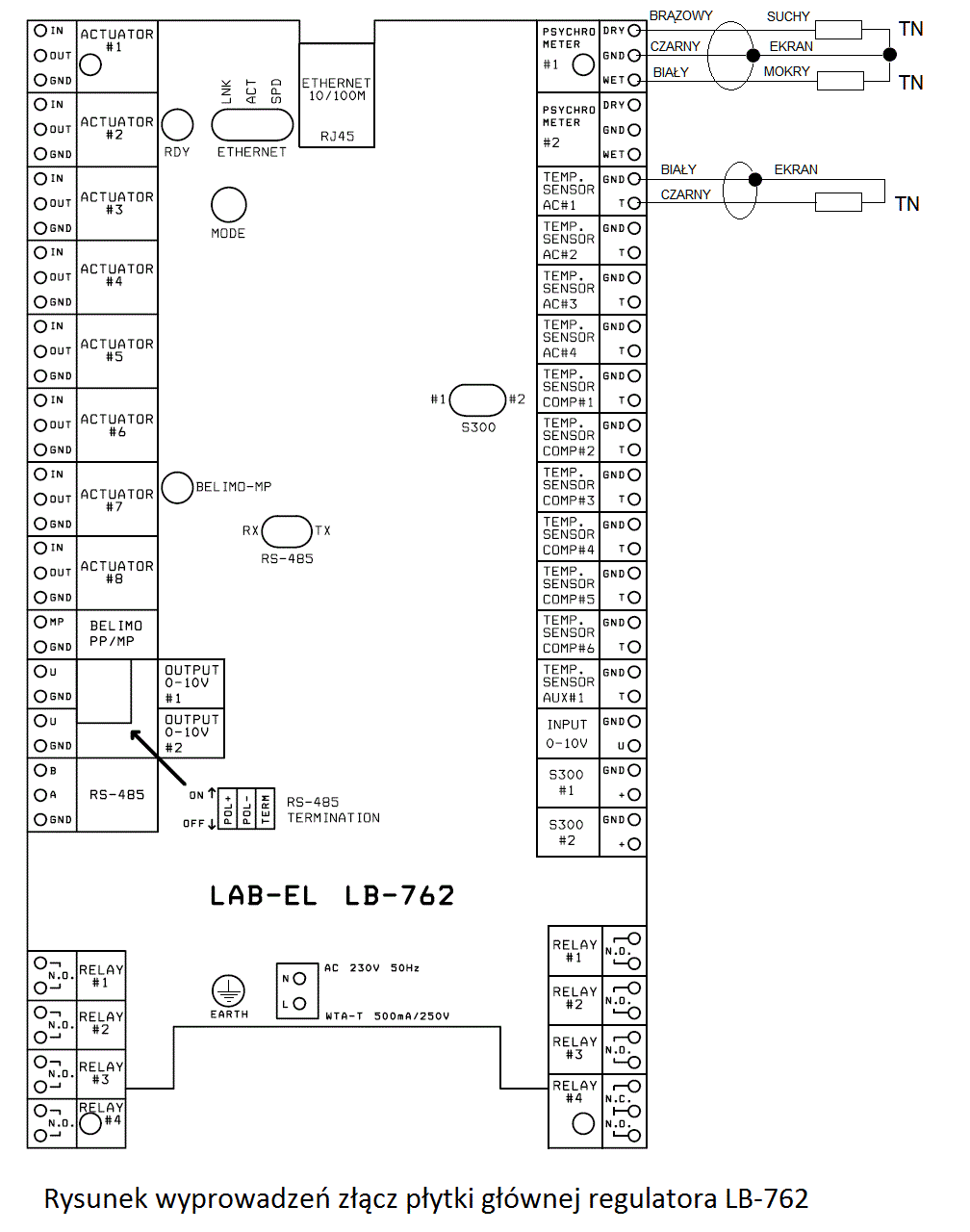
Current design of measuring probes ensures stable measurement results. In order to differentiate, the new psychrometric probes and probes for substrate temperature and air conditioning feature colour-coded outputs, they should be connected to the regulator’s plates as shown in the figure 6. Particular attention should be exercised in order not to confuse the terminals of temperature probes (T and GND terminals).
Devices interacting with the controllers
Air-conditioning central control
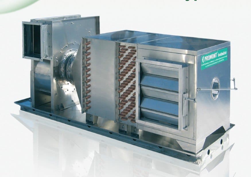
The LAB-EL mushroom-growing regulators may interact with all existing solutions for climatic channels (climatic centres). An example of an advanced centre that can deliver full air-conditioning, together with a typical arrangement of probe and working devices is presented in the upper part of Fig. 2. Circulation air from the cellar is mixed in appropriate proportions with fresh air in a mixing chamber to obtain the right CO2 concentration. The mixed air passes through a heat exchanger (cooler), through which cold water flows. When temperature drops below the dew point, the excess of air humidity is condensed on partial condensers. The air measurement is conducted before the chiller, in order to protect the cooler from freezing in winter. Then the air passes through a second heat exchanger (heater), through which hot water flows, where it is heated so that the temperature in the cellar may reach the required value. The efficiency of the cooler and the heater is adjusted via valves with proportionally acting servos, controlled via the LB-762 climate regulator. In the case of the cooler, it is enough to use a shut-off valve; in the case of the heater, a three-way valve should be used with an additional local circulating pump that maintains stable forced water circulation in the heater. After the heater there is a fan, which guarantees the air flow at a set speed, with the use of a motor powered via an inverter (frequency converter), in turn controlled via the climate regulator.
Servos and valves
With the LB-762 mushroom-growing controller any servo may be used, provided it is powered with 24 V / DC or alternate current voltage 24 V / 50 Hz and has a Y = 0…10 V / DC (or Y = 2…10 V / DC) control signal input. The servo type (for adjusting air throttles) of suitable torque should be recommended by the manufacturer of ventilation ducts. Both traditional analogue servos, as well as Belimo MP-Bus digital servos may be used.
For adjustment of cold and hot water supply we recommend using
valves with servos manufactured by BELIMO
or JOHNSON CONTROLS (e.g.
VG7000 series). The valve type must be adjusted to the size of the
climatic central and the diameter of water supply pipes. The valve type
should be recommended by the authorized designer (contractor) of the
hydraulic heating and cooling or the valve distributor. The servos
actuating the valves should be powered by 24 V / 50 Hz and must be
equipped with a Y = 0…10 V / DC (or Y = 2…10 V / DC) analogue or digital
(Belimo MP-Bus
series) control signal input.
Installation of devices
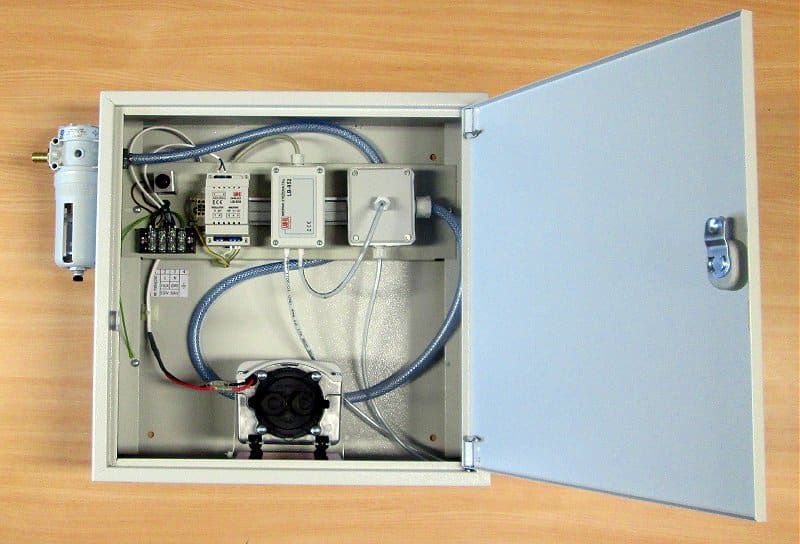
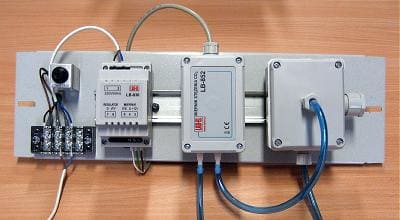
LAB-EL company delivers this basic set: the LB-762 regulators, temperature and humidity measuring probes and LBX control software for PC. Additionally, the delivery may include: an LB-480 converter or an LB-375 converter, an LB-710R thermo hygrometer with an LB-719 case, a CO2 meter LB-852 with equipment for CO2 measurement (Fig. beside) and screened computer cables (to connect the regulators with a computer). It is recommended to purchase a control computer (please remember: it must be equipped with a UPS!), printer and Internet modem (e.g. for Neostrada or the GSM/GPRS mobile network) — given the vicinity of the guarantee service — from a computer company near the place of residence. We provide additional assistance for low-voltage electric installation and system configuration (connection of probes, calibration of probes, connection and configuration of a computer, programming of parameters), as well as training. Reduced installation costs require the active participation of the investor in the installation (mechanical mounting of equipment and cabling) and the use of the investor’s own working devices.
Remark: The water must not be subject to condensation inside the CO2 meter. When a meter is used for measuring air drawn from hot and humid rooms (e.g. from a mushroom-growing cellar), there should be an external dehumidifying filter used before the meter. The CO2 meter shall be at a temperature 5…10°C higher than the room temperature from which the humid air is taken for measurement.
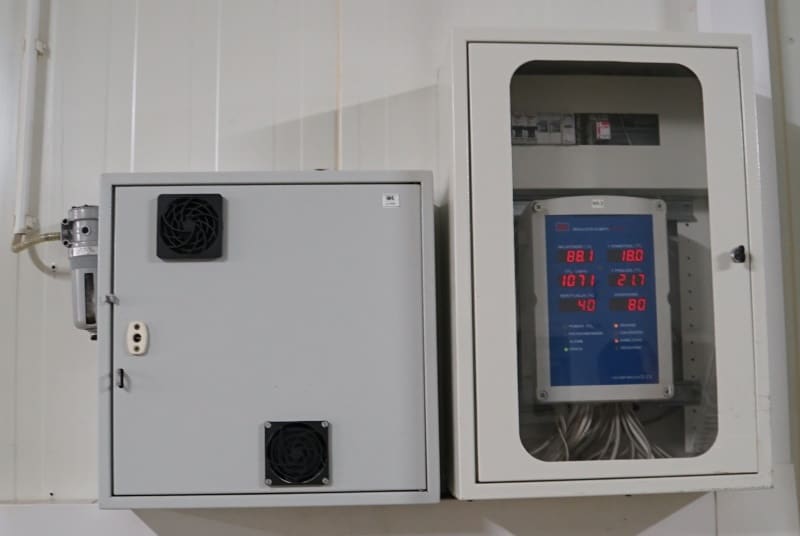
For safety reasons, the LB-762 regulators should be installed in additional SR1A enclosures, where there is room for distributing the wires from the measuring probes and the place for electrical installation together with the mains power fuses. The picture below shows the view of the LB-769W housing of the CO2 measurement unit (on the left) and the view of the LB-762 regulator in the SR1A housing (on the right side).
‘Turnkey’ installations
The electric installation for the equipment and the ‘turnkey’ installation are carried out by the cooperating companies.
LAB-EL company secures country-wide warranty service (12 months) and
full post-warranty service. The warranty service does not cover the
travelling costs incurred by a service visit at the client’s location
unless previously agreed with the installation engineer. A cost
estimate of the LB-762 regulators installation is provided on
individual demand by LAB-EL or the installation company.


